The Life and Work of Konrad Zuse (by Horst Zuse)

Part 4 (continued): The Z2 and Z3
Arithmetic Exception Handling: The Z3 included the ability to perform arithmetic exception handling. Konrad Zuse implemented this exception handling because he wanted to be sure that the Z3 would calculate numbers correctly, even when it was working without a supervisor. Thus, the Z3 was designed to recognize the following operations:
Underflow of the range of numbers is 0
Overflow of the range of numbers is infinity
For calculations involving 0:
0 + x = x
0 * x = 0
x / 0 = infinity
0 / 0 = ?
For calculation involving infinity:
infinity + x = infinity
infinity * x = infinity
1 / infinity = 0
All operations with ? have the result ?
0 / 0 = undefined
infinity - infinity = undefined
infinity / infinity = undefined
0 x infinity = undefined
The undefined state was displayed on the left-hand side of the output device using small lights. For the numbers 0 and infinity, Konrad Zuse used special bit codes in the exponent. An exponent of 63 was used to represent decimal 0, while an exponent of 64 or +63 represented ± infinity. The Z3 always performed calculations correctly if one argument was 0 or infinity and the other argument was in the allowed range.
The Z3's input and output devices
Fig.33.The Z3s input and output device. Numbers could be entered using four buttons for the mantissa and 17 buttons for the exponent.
Results were displayed using lamps.
The Z3's output device
Fig 34.The Z3s output device showing
the lamps for the decimal numbers (right)
and the arithmetic exception handling (left).

In order to display results, the binary floating-point numbers used inside the Z3 were converted to decimal floating-point numbers (each conversion required between 9 and 41 clock cycles, depending on the exponent). The mantissa consisted of 4 decimal digits (five digits for the 1) and the exponent was between 8 and +8. The biggest decimal number which could be shown was 19999E108.

Clocked Machine: The speed of the Z3 was governed by the frequency of a special impulse generator (or "clock") that was used to synchronize the machine. In fact the clock is actually an electric motor driving a shaft/drum, upon which are attached a number of "arms" (or protruding levers). Each arm was used to close a switch, which in turn activated groups of relays. The angular separation between the arms caused different switches to be closed at different times, thereby allowing the system to control the flow of data between the various units.
The Z3's clock generator The Z3's clock generator

Fig.35 (left) and Fig.36 (right). The Z3's special impulse generator (clock).
The speed of the capstan could be controlled in steps.

Konrad obviously wanted the clock frequency to be as high as possible so as to make the Z3 perform its calculations as quickly as possible. However, there was a tradeoff to be made, because higher clock speeds caused sparking of the telephone relays. The clock frequency that was eventually used was around 5.3 Hertz depending on the quality of the relays.

In talks with Rojas [ROJA98a] and myself, my father mentioned that a multiplication of two floating point numbers took about three seconds (the Z3 needed 16 cycles for a multiplication, so 16 cycles / 5.3 Hertz = 3 seconds). In order to avoid sparking of the relay contacts when switching them, he used the drum to drop off the electricity at the switching time. This principle avoided material rust and guaranteed a long functionality of the relay contacts.

Micro-Sequencer and Pipelining: The heart of the Z3s control unit consisted of micro-sequencers. Every cycle in the Z3 was divided into five steps (I to V).

The Z3's execution pipeline
Fig.37 The Z3's execution pipeline.

Steps IV and V are used to transfer information from one part of the Z3 to another; for example, the contents of a register to a memory cell. During steps I, II, and III, an addition or subtraction is executed in both parts of the arithmetic unit (this is the execution phase of an instruction). A typical instruction takes the arguments of the operation, executes an operation, and writes the result back. Konrad Zuse considered minimizing execution time to be very important, so he executed instructions using an overlapping technique (see Fig.37).

This overlapping of instructions is a type of pipelining. Although it is not well known, Konrad Zuse was awarded a patent for a pipelined computer on June 30th, 1949.

The first pipelined computer in the world
Fig.38. The first pipelined computer in the world.

Konrad Zuse's patent
Fig.39. Konrad Zuse's patent.

The title of this patent is: "Rechenmaschine zur Durchführung arithmetischer Rechenoperationen (z.B. Multiplikationen)" which translates as "Calculator for the execution of arithmetic operations (for example multiplication). This was a machine consisting of eight independent arithmetic units, each of which could execute partial arithmetic operations on certain data, which made it possible to execute these operations on large data sets.
We now return to the Z3s micro-sequencers, which Konrad Zuse implemented using stepwise relays. These sequencers, which were part of the control unit, were used to enable a sequence of repeated micro-instructions. For example, the instruction Lm is realized by a sequence of additions. In the Z3 we find micro-sequences for the instructions Lw, Lm, Li, Lu and Ld. Note that this is not the same as the modern concept of micro-programming, but is instead an example of hard-wired micro-sequencing.

The Z3's micro-sequencers
Fig.40. The Z3s micro-sequencers realized using stepwise relays.

One of the Z3's stepwise relays
Fig.41. A stepwise relay.

An Example Z3 Program (Polynomial): Let us now consider an example program for the Z3. Let us assume that we wish to calculate the polynomial:

((a4x + a3)x + a2)x + a1

Let us further assume that the values for a4, a3, a2, and a1 would first be loaded into the memory cells 4, 3, 2, and 1 using the input device.

Lu To call the input device for the variable x
Ps 5 To store variable x in memory word 5
Pr 4 Load a1 in Register R1
Pr 5 Load x in Register R2
Lm Multiply: R1 := R1 x R2
Pr 3 Load a3 in Register R2
Ls1 Add: R1 := R1 + R2
Pr 5 Load x in R2
Lm Multiply: R1 := R1 x R2
Pr 2 Load a2 in Register R2
Ls1 Add: R1 := R1 + R2
Pr 5 Load x in Register R2
Lm Multiply: R1 := R1 x R2
Ppr 1 Load a1 in Register R2
Ls1 Add: R1 := R1 + R2
Ld Shows the result as a decimal number
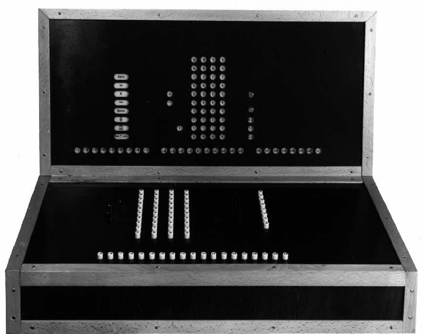
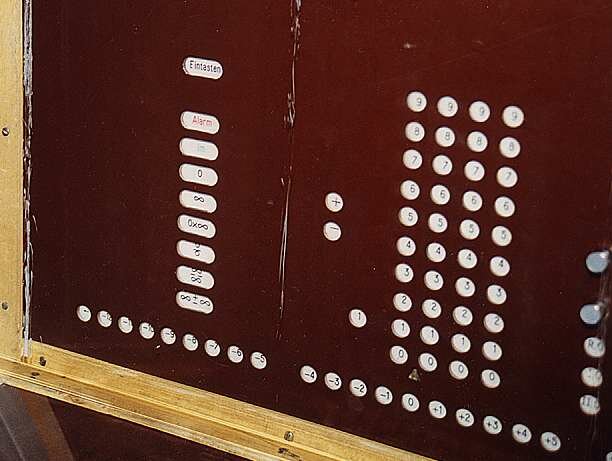
The Lu instruction at the beginning of the program instructs the input device to read a value for x. The Ld instruction at the end of the program directs the Z3 to display the result as a decimal number.

Minimal Design Principle and the Universal Computer (Turing)
Konrad Zuse followed a minimal design principle in the construction of his computers, because his goal was to build a powerful computing machine with minimal effort and cost. He really didn't have any other choice, because his parents were not rich and he didnt have much money. As far as he was concerned, the Z3 was the last in a series of trial machines (Z1-Z3) that were intended to pave the way to a machine that would be able to solve the mathematical problems of engineers and scientists.

Konrad Zuse was convinced that his computer could calculate all mathematical problems (in 1941 he told his friends that his machine was capable of playing chess), but he could not prove that this was he case. In fact it wasnt until 1998 (three years after Konrads death) that Raul Rojas [ROJA98a] formulated the proof that the Z3 was a truly universal computer in the sense of a Turing machine.

The S1 and S2 Computers
The S1 and S2 computers were mandated by the Henschel aircraft company in 1942/43. These were special developments for measuring the wings of airplanes. The S1 employed approximately 600 relays and had hardware-wired programs. The S2 was the successor of the S1, and consisted of approximately 800 relays and about 100 dial gages in order to measure the surface of the wings. It was used by the Henschel Aircraft Company since 1942. The S2 can be regarded as the first process computer in the world.

Previous Section    Return to Index    Next Section


Copyright & Contact Info

Return to EPE Online Home Page