The Life and Work of Konrad Zuse (by Horst Zuse)

Part 4 (continued): The Z2 and Z3
Now let us consider the discussion of floating-point numbers in Burks paper [BURK46], which states "It would therefore seem to us not at all clear whether the modest advantages of a floating binary point offset the loss of memory capacity and the increased complexity of the arithmetic and control circuits." (Also note that the use of the binary system for computers was proposed in John von Neumanns "First Draft of a report on the EDVAC" [NEUM45])

It is very important to note that floating-point numbers were discussed as late as 1946 by Burks et al., at which time they were still not convinced that this was a good concept. By comparison, Konrad Zuse described the concept of a floating processor in 1934 and implemented such a unit in 1936, fully ten years before Burks paper postulated it as a concept for modern computers and not as a built machine.

Now let us consider the logical concepts of the Z3 in detail:

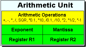
Parallel Machine: The Z3 was a parallel working machine. A 22-bit word of data could be moved from the memory to the Register R1 and vice versa in one step (clock cycle). The same holds true for the arithmetic unit, where, amongst other things, parallel adders were used.

Memory: The memory of the Z3 consisted of 64 words, each containing 22 bits. Each word was directly addressable by the instructions Pr z or Ps z, where z is the address in the range: 64 <= z <= 1. A relay was needed for each bit.

Floating Point Numbers: Konrad Zuse employed a semi-logarithm representation of numbers. Let us take the number 100. In the binary system this number can be written as:

100 = 1x26+ 1x25 + 0x24 + 0x23+ 1x22 + 0x21 + 0x20 = 64 + 32 + 4

The number 100 can be created by the power of 2 related to the numbers: 26, 25 and 22 = 64 + 32 + 4. In the binary representation we use the 1 or 0 in order to represent the number. (These are exactly the factors 1 and 0 before the multiplication sign. In the binary digit system the number 100 can be written as: 1100100. This is a binary number without a decimal point. The number 100.5 can be represented as:

100.5 = 1x26+ 1x25 + 0x24 + 0x23+ 1x22 + 0x21 + 0x20 + 1x2-1= 64 + 32 + 4 + 0.5

In the binary system we write this as 1100100.1, where the 1 to the right of the decimal point represents 2-1= 0.5 (this form of representation is known as "fixed-point"). Representing numbers using a binary (0 and 1) notation has big advantages for computers. This has not changed to the present day. Since only two states or two numbers are considered, we can use pair circuits to store numbers and to operate with them. In 1939, relays were such building blocks. However, the above representation of numbers has a disadvantage. Konrad Zuse used 22 bits for his numbers, but with integer representations 22 bits can only be used to represent small numbers in the range <= 222-1. For this reason, Konrad Zuse used the binary floating-point (semi-logarithmic) representation. Let us consider the number 100 again:

100 = 1x26+ 1x25 + 0x24 + 0x23+ 1x22 + 0x21 + 0x20= 64 + 32 + 4

Konrad Zuse divided the number into an exponent and a mantissa. In the case of our example of 100, he would have formed his exponent from the power of two of the highest exponent in our number (6). This number would then be converted into binary to give 110. Similarly, the mantissa associated with our example would have been the binary number 1100100. This would have resulted in a floating-point representation as follows:

00000110    110010000000000

Using this scheme the first digit of the mantissa is always 1. For this reason, the first 1 is ignored, leaving the mantissa as 100100 instead of 1100100. Using this technique, Konrad Zuse managed to gain an extra digit, which he could use to provide higher accuracy. That is, instead of 14 bits, he effectively had 15 bits for the mantissa. The end result is that our number of 100 would now be represented as follows:

00000110    10010000000000

So the number 100.5 in the binary system is represented as1100100.1, while the floating point equivalent is as follows:

00000110    110010010000000

In the Z3, this number would be represented as follows:

00000110    10010010000000

Using this concept, Konrad Zuse was able to handle very big and very small numbers in the range of approximately ± 2-63 to ± 263.

Examples of floating point numbers in the Z3
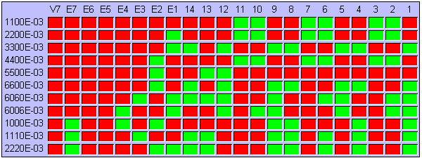
Fig.30. Examples of floating point numbers of the Z3. VZ is the sign for the mantissa, E7 to E1 are the bits of the exponent, and the numbers 14 to 1 represent the 14 bits of the mantissa. This picture is a copy of one from the Konrad Zuse Multimedia Show
[ZUSE98].

Instructions: The Z3 consisted of the following instruction set and cycles. We introduce the following notation: R1 and R2 are 22-bit wide Registers. The notation R1 := R1 + R2 means "The contents of Register R1 are added to the contents of Register R2 and the result is stored in Register R1 (Register R2 is set to empty)."
Instruction Function

Cycles

Pr z Read the contents of the memory word z into the Registers R1 or R2 1
Ps z Write the contents of Register R1 into the memory word z 0-1
Ls1 Addition: R1 := R1 + R2 3
Ls2 Subtraction: R1 := R1 - R2 4-5
Lm Multiplication: R1 := R1 * R2 16
Li Division: R1 := R1 / R2 20
Lw Square root: R1 := SQR(R1) 20
Lu To call the input device for decimal numbers 9-41
Ld To call the output device for decimal numbers 9-41
The two basic arithmetic operations of the Z3 are the addition and substraction of the exponent and signs. Addition and subtraction require more than one cycle because, in the case of floating point numbers, care has to be taken to set the size of the exponent of both arguments to the same value. This requires some extra comparisons and shifting. The number of cycles needed for the Lu and Ld instructions is variable, because it depends on the exponent of the argument. A number can be stored in memory (Ps) in zero cycles when the result of the last arithmetic operation can be redirected to the desired memory address. In this case, the cycle needed for the store instruction overlaps the last cycle of the arithmetical operations.

You may be a little surprised to note that the conditional branch instruction is missing. In his papers between 1936 and 1945, Konrad Zuse described many scientific and numerical problems he wanted to solve with his machines, but none of these problems required the use of the conditional branch.

However, in 1944, he did mention the conditional branch when he introduced Free Programs (Freie Rechenpläne) [ZUSE45, p16]. His definition was: Bei den freien Rechenplänen beeinflussen die eigentlichen Variablen den Ablauf der Rechnung. Zunächst können die bei den quasistarren Rechenplänen besprochenen Planvariablen wie variable Operationszeichen, Strukturzeichen usw. Funktionen der eigentlichen Variablen sein. Es kann z.B. die Art der Operation in einer Rechengleichung erst errechnet werden.

This translates as: With free programs the actual variables influence the execution of the calculation. First of all the variables, like operation signs and structure signs, as defined with the quasi rigid (quasi starr) programs, etc., can be functions of the actual variable. It is, for example, possible to calculate the type of operation in a calculation equation.

Arithmetic Unit and Carry Look-Ahead: The arithmetic unit of the Z3 was Konrad Zuse's masterstroke. He reduced all the arithmetic operations to addition or substraction (subtraction is an addition of the complement of one number and the number). For the realization of the addition he implemented a special switch, because he wanted to avoid using too many cycles for the addition of two binary floating point numbers. Using this switch, he could reduce the addition of two floating-point numbers from a minimum of 14 cycles (with a serial addition) to only three cycles (with a parallel addition). Although there were only five instructions for arithmetic operations (Ls1, Ls2, LM, Li, and Lw), some additional operations were implemented that could be called from the input device. He also simplified the execution of the arithmetic operations with micro-sequences controlled by stepwise relays.

Block diagram of the Z3's arithmetic unit
Fig.31. Block diagram of the Z3's arithmetic unit.
A relay from the Z3
Fig.32. A relay from the Z3.

Konrad Zuse employed a self-developed carry look-ahead circuit constructed from relays for the addition of floating-point numbers. Assuming the numbers to be added were still in the memory, then five cycles were required: two for the Pr instruction and three for the Ls1. The first cycle was used to transfer the first operand to Register R1, while the second cycle was used to transfer the second operand to Register R2. The exponent and mantissa were then added and the result was stored in Register R1 (after this Register R2 is set empty). We write this as: Ls1: R1 := R1 + R2. (Note that Konrad Zuse used additional internal registers which are not shown on the picture above. These registers were two bits longer than the mantissa in order to provide higher accuracy results.)

The Z3's multiplication algorithm is like the one used for decimal multiplication by hand. That is, it is based on repeated additions of the multiplicator according to the individual digits of the multiplicand. The division algorithm is similar to that for multiplication, except that repeated substraction is used.

The instruction algorithm behind the instruction Lw is one of the "jewels" of the Z3. The main idea is to reduce the square root operation to a division (See also the discussions on the Z4 Computer).

Previous Section    Return to Index    Next Section


Copyright & Contact Info

Return to EPE Online Home Page