Fig.11. On the brown-colored drawing board
Konrad Zuse designed the Z1 a second time.
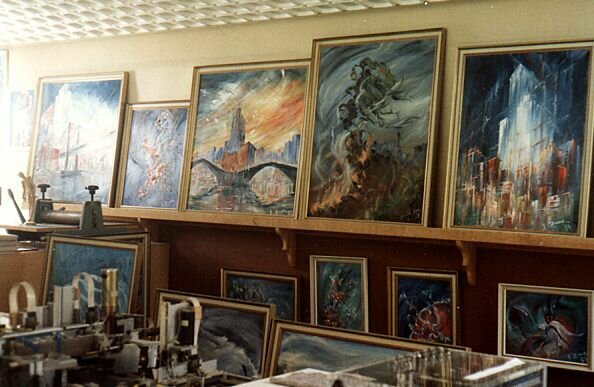
Fig.12. Another view in the atelier of
Konrad Zuse (1986).
|
The Life and Work of Konrad Zuse (by Horst Zuse) |
| Part 3 (continued): The Z1 |
|
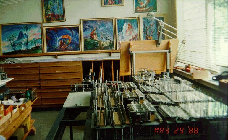
Konrad Zuse rebuilt the Z1 in his atelier in Hünfeld between 1987 and 1989. The original Z1 was privately financed by Konrad Zuse, his parents, his sister Lieselotte (1908-1953), and friends. Rebuilding the Z1 was a difficult task for my father because he was 77 years old. It was also very expensive (financially) to reconstruct all the pieces of the machine. In fact the cost of rebuilding the Z1 was around 800 000 DM. The Siemens AG coordinated a consortium of about five companies and paid the major part of the costs.
Working in his atelier, Konrad recreated thousands of engineering drawings of every piece of the machine, because the original plans were destroyed during the war. At the end of 1987 the reconstruction of the Z1 was interrupted when my father suffered a heart attack. However, after 6-months, the construction of the machine proceeded. |
|
Fig.11. On the brown-colored drawing board Konrad Zuse designed the Z1 a second time. |
Fig.12. Another view in the atelier of Konrad Zuse (1986). |
| Approximately 30,000 components for this machine -- drawn by Konrad Zuse -- were then constructed by Siemens AG in Bad Hersfeld using modern numerical machines. These components were then assembled by Konrad Zuse, an employee of Siemens AG, and two students Schweier and Saupe [SCHW89] from Köln. | |
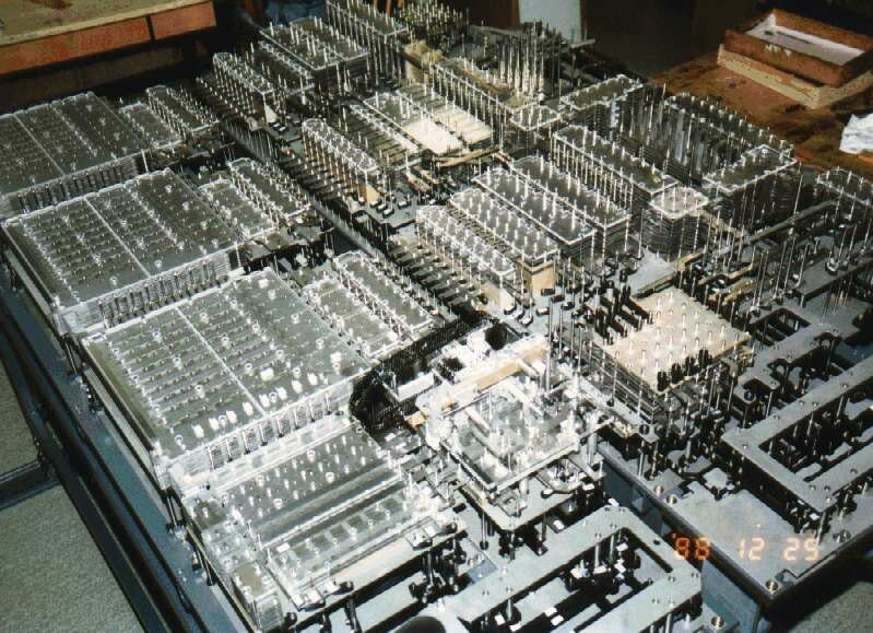 Fig.13. The rebuilt Z1 in the atelier of Konrad Zuse. (This picture was taken on December 25, 1988 by Horst Zuse) |
|
The recreated Z1, which was completed in 1989, was moved from Hünfeld to Berlin. Rebuilding the Z1 was a tremendous achievement, which allowed my father to show the world the first freely programmable computer based on binary floating point numbers and a binary switching system. |
|
As we previously discussed, the Z1 had a 64-word memory, where each word contained 22 bits. Every word was directly addressable by the punch tape and the punch tape reader together with the control unit, and data could be read from and written to each word. It is worth noting that this mechanical memory was no slower than a memory constructed using relays, but the mechanical memory required much less space. |
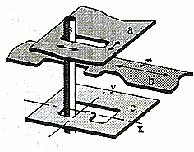 Fig.14. One bit of Zuse's mechanical memory. |
|
It is undisputed that this type of memory is unique, and Konrad Zuse obtained a patent for this memory in 1936 [ZUSE36]. The metal sheet shown in Fig.14 stores one bit. In this illustration, a binary 1 (left position) is stored (the right position equates to a binary 0). The metal sheets a and b are moveable, and are directed by the control unit to store a bit (at the clock frequency generated by the electrical engine). |
|
|
|
|
| Return to EPE Online Home Page | |