The Life and Work of Konrad Zuse (by Horst Zuse)

Part 3 (continued): The Z1
As was noted earlier, the Z1s programs (Rechenplans) were stored on punch tapes using an 8-bit code. Storing the programs on tape rather than "hard-wiring" them into the mechanism was what made the Z1 a freely programmable machine. The instruction set of the Z1 was as follows:

Pr z

Read the contents of the memory cell z into Registers R1 or R2.
Ps z Write the contents of Register R1 to the memory cell z.
Ls1 Add the two floating-point numbers in the Registers R1 and R2.
Ls2 Subtract the two floating-point numbers in the Registers R1 and R2.
Lm Multiply the two floating-point numbers in the Registers R1 and R2.
Li Divide the two floating point numbers in the Registers R1 and R2.
Lu To call the input device for decimal numbers.
Ld To call the output device for decimal numbers.
The Z1's punch tape unit.
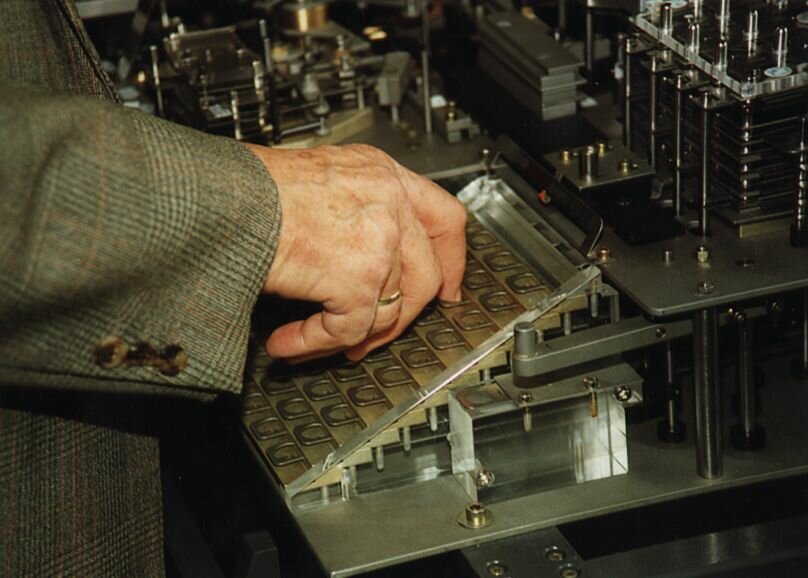
Fig.15. The punch tape (using 35mm standard movie film) and the punch tape reader of the Z1.
The full Z1. In the foreground is seen the manual crank.
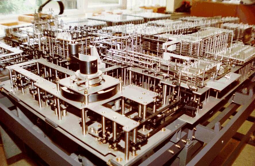
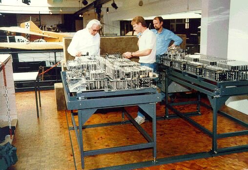
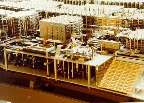
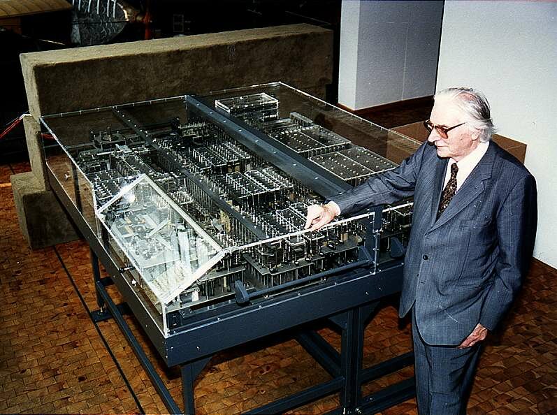
Fig.16. The full Z1.In the foreground is the manual crank for driving the clock frequency by hand.

The full Z1 is shown in Fig.16. In addition to the crank (in the foreground) for manually cycling the machine, there was also an electric motor, which was used to generate a clock frequency of one Hertz (one cycle per second). To the rear of this picture are the three blocks of memory, while the binary floating point arithmetic unit is on the right.

Z1's binary floating point arithmetic unit.
Fig.17. The Z1's binary floating point arithmetic unit. Thousands of thin metal plates were
required to implement this unit.
Is this perhaps the first computer interface?
Fig.18. The interface between the arithmetic unit (left) and the memory (right). In today's terms there was a parallel bus between the units.
If you write two floating-point numbers on a piece of paper using the binary number system, and you try to develop the algorithms to perform the basic arithmetic operations on these numbers, then you will understand just how much effort was necessary to build the Z1s arithmetic unit. My fathers design for the Z1s arithmetic binary floating point unit was ingenious. However, the technical realization using the thin metal sheets was too complex. The arithmetic unit in the original Z1 was not very reliable (similarly with the rebuilt Z1).
The Z1's input and output devices
Fig.19. The Z1's input (bottom right) and output devices (middle of picture).
Konrad Zuse inputs some data into the Z1
Fig.20. Konrad Zuse enters a decimal number into the input device (above the keys the exponent could be set from +8 to -8.
The Z1 had decimal input- and output devices. The numbers were presented to the machine in a decimal form with an exponent. The Z1 then converted the decimal numbers to a binary normalized floating point representation. Similarly, the output device converted the binary floating point number in Register R1 into a decimal number with an exponent.
The output device was realized as an annunciator
Fig.21. The output device was realized
as an annunciator. The exponent is marked
red at the bottom.
Adjusting the metal sheets and pins
Fig.22. Adjusting the metal
sheets and the pins.

Thus, as early as 1936-1938, the Z1 exhibited almost all of the facilities of the so-called von Neumann machine [NEUM45], [BURK46]. In fact the only feature that was not implemented was loading the program into the Z1s memory. This was because building a large memory was a very expensive task at that time. The calculation of a determinant (third grade) requires about 50 instructions and 15 words of memory for the variables and the intermediate results. This simple example shows that storing the program in memory would block the idea of a freely programmable machine.

Konrad Zuse with the rebuilt Z1 (1989)
Fig.23. Konrad Zuse with the rebuilt Z1 in the Deutsche Technik Museum in Berlin in September 1989.

Previous Section    Return to Index    Next Section


Copyright & Contact Info

Return to EPE Online Home Page